1. What is busbar twisting?
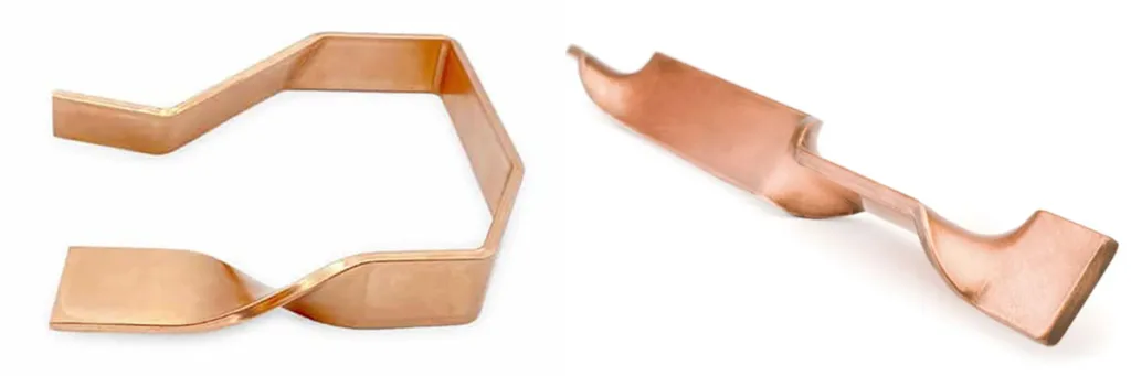
Busbar twisting is a critical processing technique for copper or aluminum busbars within the power distribution industry; it is employed to alter the orientation of a busbar during installation. Distinct from flat bending and edge bending (what is edge bending?), twisting involves rotating the busbar around its longitudinal central axis—typically by an angle of 90° or 45°.
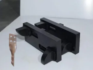
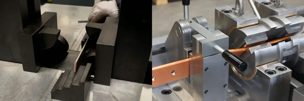
This process is typically executed using a CNC busbar bending machine, ensuring that the twisted section remains free of cracks or significant creases, and that the twist length complies with relevant standards to guarantee optimal current-carrying performance.
2. The Function of Busbar Twisting
Change Phase Connection Plane
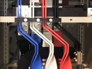
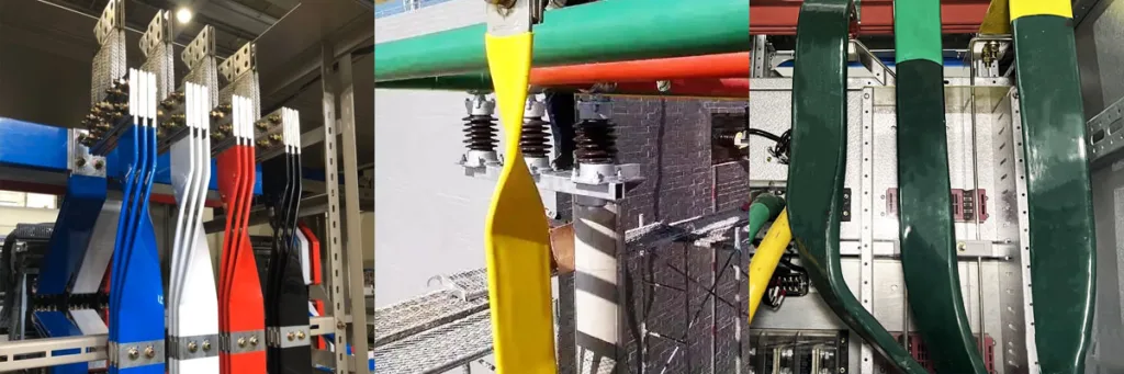
By performing a 90° twist, the busbar is reoriented from a “flat” to an “upright” position, thereby ensuring that the busbar’s contact surface aligns perfectly and flushly with the component’s terminals, thereby guaranteeing the effectiveness of the electrical connection.
Optimize the internal layout of the cabinet
Within the confines of a compact enclosure, a twisted configuration eliminates the need for complex adapters or multiple L-shaped elbows, resulting in a more direct and compact routing layout. This twisted design not only reduces the number of components but also significantly decreases the bending radius, thereby contributing to a lighter overall device.
Enhancing Electrical and Thermal Performance
Compared to achieving directional changes through the bolted lap-joining of multiple components, twisting is a single-piece forming process that introduces no joints and zero additional electrical resistance, thereby fundamentally mitigating the risk of temperature rise at connection points. Furthermore, within specific airflow designs, twisting allows for the reorientation of the busbar—for instance, shifting it from a horizontal to a vertical position—which facilitates more effective utilization of air convection and enhances the busbar’s natural heat dissipation efficiency.
Balanced Electromagnetic Force
In high-current systems, adjusting the relative spatial positioning of the busbars through twisting allows for the partial balancing of three-phase electromagnetic repulsive forces, thereby enhancing the mechanical strength of the system during short-circuit faults.
Reduce Production and Material Costs
The twisting process requires no additional adapter bars, connecting plates, or accompanying bolts and washers, thereby saving on material costs. On a CNC busbar processing machine, the twisting operation can be completed in just a few seconds. Compared to the manual process—which involves cutting, bending multiple busbar segments, and then drilling holes and tightening bolts—twisting significantly boosts assembly efficiency.
Reduce Points of Failure
There is a well-known maxim in power systems: “The fewer the connections, the safer the system.” Twisting eliminates the potential hazards of poor contact caused by loose bolts or oxidation.
3. Characteristics of the Twisting Process
Directional Flip
While traditional flat or vertical bending alters the busbar’s extension path (e.g., from a straight line to an L-shape), twisting achieves a 90° rotation of the cross-sectional orientation while maintaining the busbar’s straight-line trajectory.
Planar Adaptation
It perfectly resolves the issue of “spatial misalignment” between vertically distributed switch contacts and horizontally arranged main busbars.
Zero Joints
Compared to the use of additional “adapter strips” or “L-shaped connectors,” the twisting process forms the structure in a single continuous piece, resulting in no physical joints.
Electrical Safety
The reduction in bolted connections eliminates potential contact resistance and the risk of temperature rise caused by loosening, thereby significantly enhancing the system’s current-carrying stability and safety.
High Stress Gradient
During the twisting process, the tensile stress at the edges of the busbar is significantly greater than that at the center point. This places extremely stringent demands on the material’s properties (such as the annealing state of T2 copper).
Springback Characteristics
Metals possess an elastic modulus; consequently, the “springback” phenomenon observed after twisting is more complex than that of standard bending operations. Precise angular compensation—typically involving an over-twist of 3° to 5°—must therefore be applied via the CNC busbar processing system.
Ultimate Space Efficiency
Within densely packed switchgear or bus duct systems(What Is Bus Duct System?), the twisted configuration requires no bending radius; instead, it requires only a short linear distance (the twist pitch) to complete phase transposition, thereby enabling the design of more compact enclosures.
Material Reduction
Eliminates the need for additional accessories such as busbar connectors, bolts, flat washers, and spring washers, thereby reducing overall material costs and assembly time.
Torque Control
The torque (L) must be maintained at L ≥ 2.5 × Width; otherwise, the edges will inevitably crack.
Axial Alignment
The machine must ensure that the axis of rotation coincides with the centerline of the busbar; otherwise, the twisted busbar will suffer from severe geometric distortion (i.e., it will be twisted out of shape).
Mold Precision
Specialized molds must incorporate protective features to ensure that the tin plating or surface finish of the busbar remains undamaged under immense shearing forces.
| Feature Dimensions | Cable Knitting Technique | Standard Bending (Flat / Vertical) |
|---|---|---|
| Spatial Form | 3D Rotation, Path Unchanged | 2D Steering, Path Changing |
| Number of parts | 0(Self-forming busbar) | Extensive (may require splicing multiple segments) |
| Machining Difficulty | High (Requires precise calculation of torque and springback) | Middle |
| Electrical Advantages | Low resistance, no hot spots | Contact resistance is present at the connection point. |
4. Common Quality Defects in Busbar Twisting and Their Solutions
Torsion Center Offset
- Phenomenon: The axis of the busbar following torsion is no longer collinear with the original axis, resulting in a misalignment of the connection points at both ends.
- Cause: Insufficient mold clamping force or poor mold alignment results in displacement of the busbar during the twisting process.
- Solution: Optimize the twist length. Strictly adhere to the standard requiring that the twist length L ≥ 2.5 times the busbar width.
Surface Indentations and Scratches
- Phenomenon: Significant die marks, scratches, and even peeling copper chips appear in the torsional deformation zone.
- Cause: The surface roughness of the mold is insufficient, or the mold edges are excessively sharp, resulting in damage to the busbar surface during intense friction.
- Solution: Mold Modification—Employ “rolling” or “smooth” contact; polish and chrome-plate the mold’s contact surfaces to minimize friction; and design a larger rounded transition (R-radius) at the mold’s material entry point to prevent sharp-angled cutting.
Click View:Factors Affecting the Smoothness, Precision, and Scrap Rate of Busbar Cross-Section Processing
Torsional Crack
- Phenomenon: Microcracks appear at the four corners of the busbar; in severe cases, the cracks extend inward.
- Cause: The torsion length (i.e., the span of the twisted section) is too short, resulting in excessive stress concentration in the material; alternatively, the hardness of the copper busbar is too high (e.g., due to a suboptimal T2 temper).
- Solution: Utilize a Siemens PLC system for angle presetting. Set springback compensation coefficients tailored to different materials (copper vs. aluminum)—for instance, setting the angle to 92° to compensate for 2° of springback.
Angular Springback and Torsion Out-of-Tolerance
- Phenomenon: When set to a 90° twist, the part rebounds to 85° or 87° after unloading; furthermore, batch processing consistency is poor.
- Cause: Non-uniform material hardness, and the lack of precise angle feedback control in standard hydraulic systems.
- Solution: Employ a “limited-position clamping” mold structure to fully lock down both ends of the busbar prior to the commencement of rotation.
5. Quality Assurance and Testing Methods
A. Key Control Points for Quality Assurance
- Material Admission System: The oxygen content and annealing state of copper and aluminum busbars are subject to rigorous inspection. For twisting operations, T2-grade copper busbars in either the soft (M) or semi-hard (Y2) temper are mandatory. Hard-temper (Y) copper busbars must undergo localized annealing prior to processing; otherwise, they are highly susceptible to intergranular fracture.
- Mandatory Torque Standard: Strictly adhere to the process “red line” of L ≥ 2.5 × W. During CNC programming, if the calculated torque is insufficient, the torsional length must be compensated for by modifying the routing path.
- Precision Die Alignment: The rotational axis of the knurling die must be verified whenever specifications are changed. If the axis deviation exceeds 0.5 mm, an eccentric force will be generated along the generating line, resulting in uneven stress distribution across the cross-section and, consequently, a reduction in service life.
- Constant-Speed Machining: Avoids torsional shock. A servo system is utilized to control the rotational speed, allowing sufficient time for metal lattice slip and thereby minimizing the accumulation of internal stress.
B. Quality Inspection Indicators
| Test Items | Technical Requirements | Detection Tools | Conclusion Determination |
|---|---|---|---|
| Appearance Quality | The surface is smooth, free of cracks and electrical erosion damage | 5x Magnifying Glass | Cracks are classified as a "Class I defect" and result in immediate scrapping. |
| Twist Angle | 90°±1° | Digital Angle Finder | Exceeding tolerances compromises installation precision |
| Surface Coating | The tin plating exhibits no peeling and no exposed copper | Visual estimation | Affects corrosion resistance |
| Mechanical Damage | Indentation depth< 0.2mm | Depth Gauge | Excessive depth will cause stress concentration |
| Verticality | Parallelism of the two end faces after torsion≤1mm | Feeler Gauge + Surface Plate | Factors Affecting Bolt Clamping Force Distribution |